GLB1811E_KN_img_01psd.png

knx_logo_01psd.png
GLB1811E_KN_img_01psd.png
knx_logo_01psd.png

LK0

With digital KNX bus interface


Compact unit for VAV terminal units TVR, TVJ, TVT, TZ-Silenzio, TA-Silenzio, TVZ, TVA and TVM

  • Controller, dynamic effective pressure transducer and actuator in one casing
  • Use in ventilation and air conditioning systems, only with clean air
  • Volume flow rates qvmin and qvmax are factory set and and stored in the controller (but can be changed)
  • Data transparency due to bus communication
  • Communication interface KNX (S-mode, LTE-mode and PL-link)
  • Setpoint value default setting, override control and parameter adjustment by means of bus communication
  • Service access for manual adjustment devices and PC configuration software

General information


Application

  • All-in-one control device for VAV terminal units
  • Dynamic differential pressure transducer, electronic controller, and actuator are fitted together in one casing
  • Choice of various control options based on setpoint value default setting
  • Setpoint value defaults and override controls by means of communication with a higher-level system
  • Support of central BMS optimisation functions by providing network communication
  • The volume flow rate actual value is available as a network data point
  • The damper blade position is available as a network data point
  • Standard filtration in comfort air conditioning systems allows for use of the controller in the supply air without additional dust protection 

With heavy dust levels in the room

  • Install suitable exhaust air filters upstream because a partial volume flow is routed through the transducer for volume flow rate measurement

If the air is contaminated with fluff, sticky components or aggressive substances

  • Use a control component with static differential pressure transducer


Control strategy


  • The volume flow controller works independent of the duct pressure
  • Differential pressure fluctuations do not result in permanent volume flow rate changes
  • To prevent the control from becoming unstable, a dead band is allowed within which the damper blade does not move
  • The flow rate range for the controller is set in the factory
    • qvmin: Minimum volume flow rate
    • qvmax: Maximum volume flow rate
  • Operating parameters are set in the factory according to the order code


Operating parameters


  • qvmin  = 0 – 100% of the nominal volume flow rate qvnom adjustable
  • qvmax  = 20 – 100% of the nominal volume flow rate qvnom adjustable
  • If necessary for special applications, customers can use setting ranges that are different from the factory settings. Be sure to see the Siemens basic documentation for GLB181.1E/KN for information


Operating modes


  • Variable operation (V): The setpoint defaults at the KNX digital bus interface
  • Constant value operation: A constant setpoint defaults or can be entered


System environments


  • Building automation with Siemens peripheral bus PL-link (Desigo Total Room Automation)
  • Building automation with KNX LTE-mode (Siemens Synco 700 from product type C)
  • Building automation with KNX S-mode (third-party integration and free programming) 
  • Support for ETS device profiles v1.x and v2.x


Parts and characteristics

  • Transducer for dynamic measurements
  • Overload protection
  • Release button to allow for manual operation 
  • 2 connecting cables (supply voltage, communication) with 2 wires each
  • Service interface for service tools
  • Status LED for supply voltage and errors
  • Push-button for starting test functions and activating the programming mode
  • Removable address sticker with unique KNX ID (both alphanumeric and as a barcode)
  • The KNX-certified Compact controller can be used with all KNX devices suitable for the desired application, provided that the required data points are available


{1902}


{1907}


{1908}


Operating parameters


  • qvmin  = 0 – 100% of the nominal volume flow rate qvnom adjustable
  • qvmax  = 20 – 100% of the nominal volume flow rate qvnom adjustable
  • If necessary for special applications, customers can use setting ranges that are different from the factory settings. Be sure to see the Siemens basic documentation for GLB181.1E/KN for information


Information technique

Function, Specification text, Order code

  • Function
  • SPECIFICATION TEXT
  • ORDER CODE
      Principle of operation Functional_graphic_LK0.png


① Differential pressure transducer

② Actuator


③ Volume flow controller

④ Setpoint via KNX communication interface


VAV terminal units control the volume flow in a closed loop, i.e. measurement – comparison – correction. For volume flow rate measurement the effective pressure is measured first. This is done via a differential pressure sensor. The integral differential pressure transducer transforms the effective pressure into a voltage signal. The volume flow rate actual value is available as a network data point. The factory setting is such that 100% correspond to the nominal volume flow rate (qvnom). The volume flow rate setpoint value comes from a higher-level controller (e.g. room temperature controller, air quality controller, central BMS). Variable volume flow control results in a value between qvmin and qvmax. It is possible to override the room temperature control, e.g. by a complete shut-off of the duct. The controller compares the differential pressure setpoint value to the actual value and controls the actuator accordingly if there is a difference.


Category


  • Compact controller for volume flow rate


Control strategy


  • The volume flow controller works independent of the duct pressure
  • Differential pressure fluctuations do not result in permanent volume flow rate changes
  • To prevent the control from becoming unstable, a dead band is allowed within which the damper blade does not move
  • The flow rate range for the controller is set in the factory
    • qvmin: Minimum volume flow rate
    • qvmax: Maximum volume flow rate
  • Operating parameters are set in the factory according to the order code


Interface


  • Digital bus communication with KNX 
  • KNX-TP, galvanically isolated
  • Communication interface KNX (S-mode and LTE-mode)
  • Communication interface KNX PL-link (Siemens peripheral bus)
  • Group objects for setpoint value default setting, override control, volume flow rate actual value, damper blade position and status


Commissioning


  • As the operating values are factory set, the terminal units have to be installed at the specified locations
  • Commissioning requires basic knowledge on how to use the required project planning and commissioning tools


TVRD / 100 / D2 / LK0 / V / qvminqvmaxm³/h
||||||||
1256781011

1 Type
TVR VAV terminal unit 

2 Acoustic cladding
No entry: none
D With acoustic cladding 

3 Material
Galvanised sheet steel (Standard construction)
P1 Powder-coated RAL 7001, silver grey
A2 Stainless steel construction 

5 Nominal size [mm]
100, 125, 160, 200, 250, 315, 400 

6 Accessories

No entry: none
D2 Double lip seal both ends
G2 Matching flanges for both ends 

7 Attachments (control components)

LK0 Compact controller, dynamic transducer, KNX interface 


8 Operating mode
V Variable (setpoint value range)   

10 Operating values for factory setting
Volume flow rates in m³/h or l/s
qvmin 
qvmax  

11 Volume flow rate unit
m³/hl/s


Order example: TVT/200×100/D2/LK0/V/200-800 m³/h
Acoustic claddingNone
MaterialGalvanised sheet steel
Nominal size200 × 100 mm
AccessoriesDouble lip seal both ends
AttachmentCompact controller, dynamic transducer, KNX interface
Operating modeV variable operation
Volume flow rate200 – 800 m³/h
 

Variants

  • VARIANTS
  • LÖSCHEN
Compact controller GLB181.1E/KN GLB1811E_KN_gc_01ai.png

① Rotation stop

② Clamping device

③ Position indicator

④ Indicator light

⑤ Push button

⑥ Service socket

⑦ Gear release button (side)

⑧ Connections for differential pressure sensor

⑨ Connecting cable


Technical data, Product details

  • TECHNICAL DATA
  • PRODUCT DETAILS


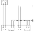
Compact controllers for VAV terminal units


VAV terminal units

Type of installation componentPart number
TVR, TVJ, TVT, TZ-Silenzio, TVZ, TVAGLB181.1E/KNA00000043586
TVM2 × GLB181.1E/KNA00000043586


,

Measurement principle/installation orientation

Dynamic measurements, any installation orientation


Supply voltage/frequency24 V AC ± 20%, 50/60 Hz
SELV (Safety Extra Low Voltage) or PELV (Protective Extra Low Voltage)

Functional range

19.2 V – 28.8 V AC
Power consumption – when running3 VA / 2.5 W
Power consumption – when idle1 VA / 0.5 W
Torque10 Nm
Run time for 90°125 s (60 Hz) – 150 s (50 Hz)
Bus interfaceKNX, TP1-256 (electrically insulated), current consumption of the bus: 5 mA
AddressingFor example, assignment of physical addresses to the unique KNX IDs on the compact controllers (by others, using commissioning tools)
Setpoint / actual value interfacewith KNX group objects
Connections (supply voltage/communication)2 connecting cables supply/communication separated
each approx. 0.9 m, with 2 wires 2 × 0.75 mm²
IEC/EN protection classIII (protective extra-low voltage)
Protection level

IP 54

EMC

EMC to 2014/30/EU
Weight0.6 kg

,

,


Product details


Bus mode

  • The customer's bus network has to be commissioned in order to ensure smooth data exchange
  • See the sections on Commissioning and Project design and commissioning tools


Setpoint value default setting

  • The setpoint value defaults as a percentage value via KNX group objects
  • The percentage value refers to the volume flow rate range specified by qvmin – qvmax .
  • If qvmin = 0 and qvmax = qvnom are set, the entire flow rate range of the VAV terminal unit is available to the building automation system. The volume flow rate range that can be controlled depends on the VAV terminal unit type.
  • Volume flow rate range qvmin – qvmax is set in the factory according to the order code
  • Subsequent adjustment of qvmin or qvmax is possible using service tool AST20 or the customer's network
  • If just one constant setpoint value is used, the Compact controller works as a constant volume flow controller


Actual value as feedback for monitoring or tracking control

  • The volume flow rate actual value is available in m³/h and as a percentage value at the bus connection. The 0 – 100 % range corresponds to the flow rate range 0 – qvnom
  • In addition to the flow rate actual value, the actual damper blade position can be read using an additional data point


Override control

For special operating situations, the volume flow controller can be put in a special operating mode (override control) 
. The following modes are available: damper blade OPEN or damper blade CLOSED.
This can be activated by setting specific values:

  • For OPEN position: qvmax = 100 % and setpoint value = 100 %
  • For CLOSED position: qvmin < 0 % and setpoint value = 100 %


Override control for diagnosis
This can be activated using the bus system, AST20 or PC software. 


Commissioning
Configuration of the communication interface is required. For this purpose, the controller carries a removable address sticker with the unique KNX ID (both alphanumeric and as a barcode). Commissioning requires basic knowledge on how to use the required project planning and commissioning tools More communication parameters may have to be set.


Project design and commissioning tool

Interface mode Project design and commissioning tool
KNX S-modeKNX Association ETS4, ETS5,
KNX LTE-modeSiemens Synco ACS790
Siemens peripheral bus PL-linkSiemens Desigo ABT, SSA


Supplementary manufacturer documentation

  • Data sheet (N3547) VAV compact controller KNX PL-link
  • For additional, detailed information about this control component see the Siemens HIT portal. See https://hit.sbt.siemens.com/ – search for GLB181.E/KN
  • Detailed technical information P3547 on the controller
  • Installation manual M3547

,

,

,

Téléchargements

Information produit

Certificats

production {"X-Frame-Options"=>"SAMEORIGIN", "X-XSS-Protection"=>"1; mode=block", "X-Content-Type-Options"=>"nosniff", "X-Download-Options"=>"noopen", "X-Permitted-Cross-Domain-Policies"=>"none", "Referrer-Policy"=>"strict-origin-when-cross-origin", "Content-Security-Policy"=>"frame-ancestors 'self' https://api.scrivito.com https://punchoutcommerce.com https://www.trox.de https://trox-extern.com https://psp40.onventis.com https://psp22.onventis.com https://trox4u.troxgroup.com", "Strict-Transport-Security"=>"max-age=31536000; includeSubDomains", "Content-Type"=>"text/html; charset=utf-8"}

Partager la page

Recommander cette page

Vous avez la possibilité de recommander cette page en partageant le lien.

Les champs marqués d'une étoile (*) sont obligatoires.

Contact

Merci pour votre message !

Votre recommandation a été envoyée et sera bientôt reçue par le destinataire.

Contact

Nous sommes à votre disposition

Veuillez spécifier le sujet de votre requête et vos coordonnées.
Tel.: +33 1 56 70 54 54

Les champs marqués d'une étoile (*) sont obligatoires.

Contact

Merci pour votre message !

Votre message a été reçu par le Centre de Service et est en cours de traitement.
Notre département des demandes de service vous contactera sous peu.
Si vous avez des questions d'ordre général sur nos produits et services, vous pouvez également nous contacter à l'adresse suivante:
Tél .: +49 (0) 2845 2020 | Fax: +49 (0) 2845 202265

Contact

Nous sommes à votre disposition

Veuillez spécifier le sujet de votre requête et vos coordonnées.
Tel.: +33 1 56 70 54 54

Pièce jointe (max. 10MB)

Les champs marqués d'une étoile (*) sont obligatoires.

Contact

Merci pour votre message !

Votre message a été reçu par le Centre de Service et est en cours de traitement.
Notre département des demandes de service vous contactera sous peu.
Si vous avez des questions d'ordre général sur nos produits et services, vous pouvez également nous contacter à l'adresse suivante:
Tél .: +49 (0) 2845 2020 | Fax: +49 (0) 2845 202265